Boundary First Flattening (BFF) is a free and open source application for surface parameterization. Unlike other tools for UV mapping, BFF allows free-form editing of the flattened mesh, providing users direct control over the shape of the flattened domain—rather than being stuck with whatever the software provides. The initial flattening is fully automatic, with distortion mathematically guaranteed to be as low or lower than any other conformal mapping tool. The tool also provides some state-of-the art flattening techniques not available in standard UV mapping software such as cone singularities, which can dramatically reduce area distortion, and seamless maps, which help eliminate artifacts by ensuring identical texture resolution across all cuts. BFF is highly optimized, allowing interactive editing of meshes with millions of triangles.
The BFF application is based on the paper, “Boundary First Flattening” by Rohan Sawhney and Keenan Crane.
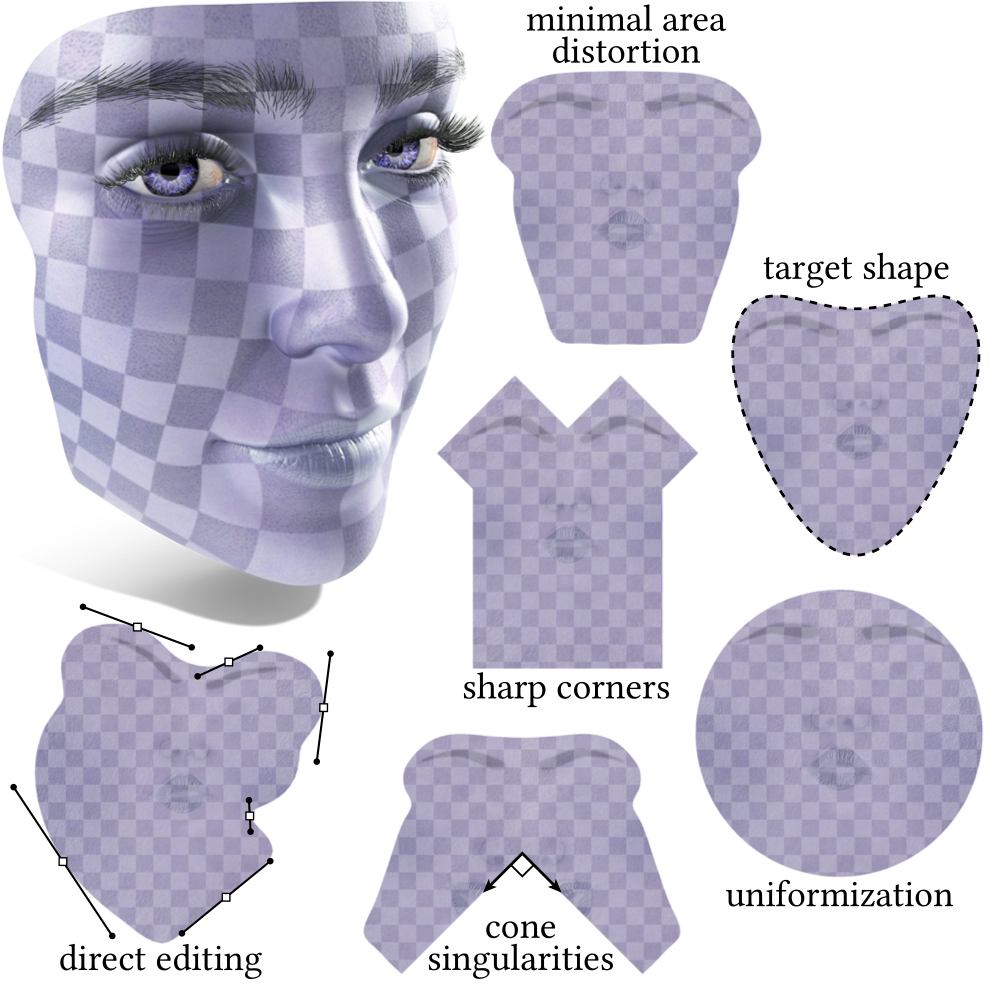
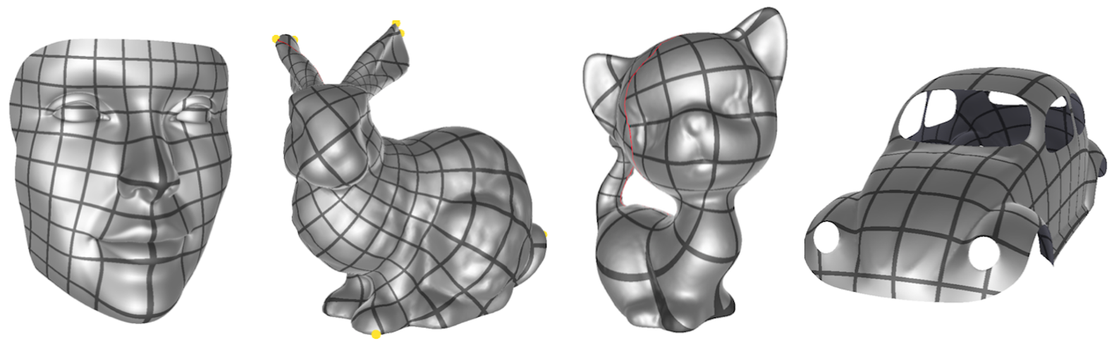
Feature Gallery
-
Minimal Area Distortion — By default, BFF automatically produces a flattening with minimal area distortion and virtually zero angle distortion. This map is generally useful for most texturing and surface processing tasks.
-
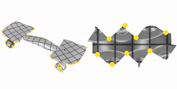
Direct Editing — The initial map can be edited interactively using handle-based manipulation of the size and orientation of the boundary curve. This can be useful for packing UVs into a texture atlas, or for emphasizing regions of the surface that should receive more texture area (for instance).
-
Sharp Corners — The domain can also be flattened into a polygon with sharp corners, like a rectangle (useful for, e.g. maximizing use of texture area).
-
Cone Singularities — Cone singularities can be used to reduce area distortion in regions of high curvature. Cones can be placed manually or automatically, and can be adjusted interactively. Optionally, the resulting map can be made globally seamless along any cuts caused by the placement of cones.
-
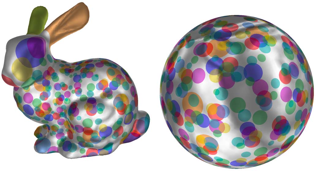
Uniformization — The surface can be mapped to a circular disk (or sphere), which is useful for cross-parameterization (mapping one surface to another).
Download Application

Release History
- v1.0 (December 2017) — Initial release.
- v1.1 (January 2019) — Adds support for arbitrary topology (holes, handles, etc.; not just disk and sphere), quad and polygon meshes, command-line interface with no GUI build dependencies, and 3x overall speedup across load/solve/write operations.
- v1.2 (June 2019) — Ensures that vertex ordering in the input/output meshes agree; accelerates cone computation for surfaces with boundary; minor accelerations and bug fixes.
- v1.3 (August 2019) — Adds support for tighter bin packing; ensures vertex ordering is preserved; more error logging and bug fixes.
- v1.4 (June 2020) — Improved spherical parameterization; bin packing related bugfixes and more efficient loading of models with many components.
Tutorial
BFF should be fairly intuitive to use, so go ahead and give it a try! If you find you still have questions, the tutorial below may provide some useful guidance. (Warning: As with most tutorials, this one may not be in sync with the latest software version. Read at your own risk! ;-))
BFF can be run either from the command line, which provides automatic parameterization and some basic operations, or in an interactive GUI, which provides additional operations and editing capabilities. Either tool loads a polygon mesh in OBJ format, and produces a flattened mesh (also in OBJ format). Meshes with (and without) boundary, holes, handles and multiple components are supported. The only restriction is that meshes must have manifold connectivity (though this may be relaxed in future versions). Meshes that do not have disk or sphere topology will be automatically cut for flattening.
Overview Video
To get started, take a look at our short (10min.) overview video. More detailed descriptions of individual features are found below.
Interactive Graphical Interface
Initially, the GUI should look something like this:
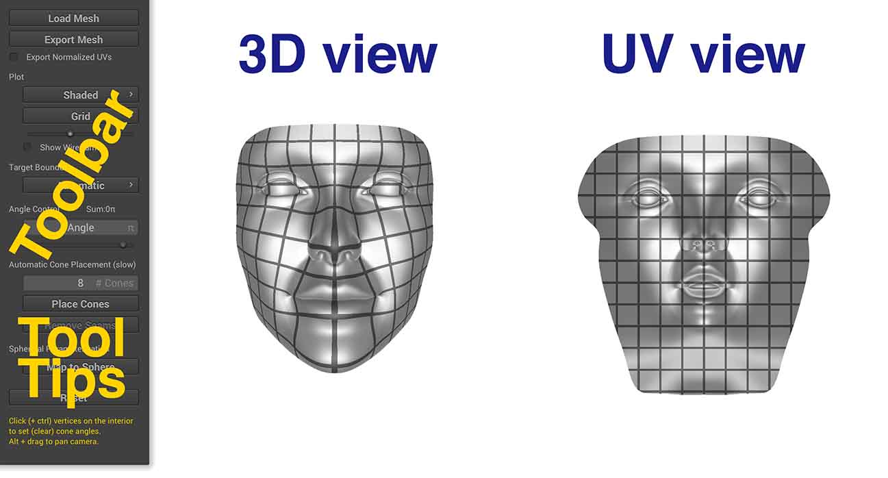
The 3D View shows the original mesh, the UV view shows the current flattening. Since BFF is incredibly fast, you do not have to take any action to get an updated flattening; the UV view will be automatically refreshed whenever you click on a button or other UI element. The Toolbar provides various options for flattening the surface; pay close attention to the Tool Tips, which can provide useful information about the currently selected tool. By default, the UV map is visualized as a grid on the surface; the shading on the surface is also used to light the UV map, to give a sense of correspondence between 3D and 2D. Additional visualization options are described below. Finally, the Reset button will set the current tool (and the corresponding flattening) back to its default parameters.
New meshes can be loaded by pressing the Load Mesh button; the Export Mesh button allows a mesh to be exported to OBJ format, with the texture coordinates stored in the vt field (one per distinct triangle corner in the flattened mesh). The Export Normalized UVs checkbox will scale the UVs between 0 and 1 in texture space.
Adjusting the View
The view can be independently adjusted in both the 3D view and the UV view. In particular:
- rotate — click and drag on any point in the background (not on the mesh)
- translate — alt/option-click on the background
- zoom in/out — scroll up/down
Visualization Options
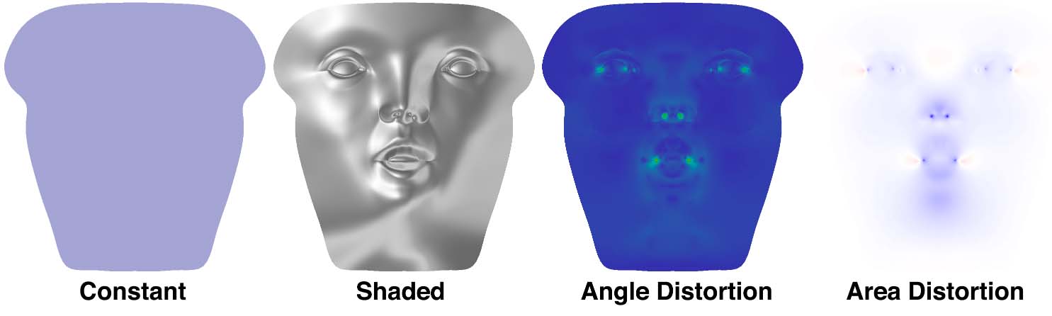
In addition to visualizing the map itself, BFF provides facilities for inspecting the quality of the map. The Shading Menu (first menu in the Plot section) provides the following options:
-
ConstantNo special shading; useful for looking at the wireframe or checking for local overlaps. In this view, flipped triangles (which are fairly rare) will be drawn in bright red.
-
ShadedThe mesh in the UV view will be lit using the shading from the 3D view. This shading gives a quick way to see which features get mapped where.
-
Conformal DistortionShows angle distortion in the mapping. Blue means no angle distortion, green means a little angle distortion, and red means a lot of angle distortion. For reasonably nice meshes (e.g., smallish triangles, not too crazy aspect ratios) you should see very little angle distortion. Large angle distortion on simple models may indicate that there is something wrong with your mesh (e.g., long invisible slivers or near-degenerate elements). In this mode, the total angle distortion will be printed out above the Shading Menu (this quantity is the average and maximum quasi conformal distortion, where 1 means no distortion).
-
Area DistortionShows how much area is distorted by the mapping. White means no area distortion, blue means shrinking, and red means expansion. In this mode, the total area distortion will be printed out above the Shading Menu (this quantity is the average and maximum log conformal factor, where zero means no distortion).
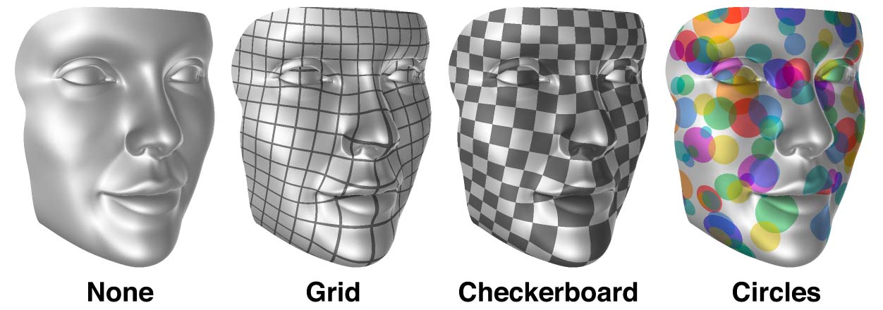
The Pattern Menu draws different patterns on the surface. These patterns have been chosen to give a sense of the angle and area distortion in the flattening. For a perfect map (i.e., no distortion at all) the pattern should look uniform in scale across the whole surface, and circles and squares in the UV view should look like circles and squares in the 3D view (taking perspective distortion into account). These features will give you a sense of how textures and other data will look when mapped onto the surface. In particular:
-
NoneNo pattern is displayed. Useful for getting a clear view of other features of the map (e.g., area distortion, or the wireframe).
-
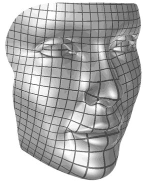
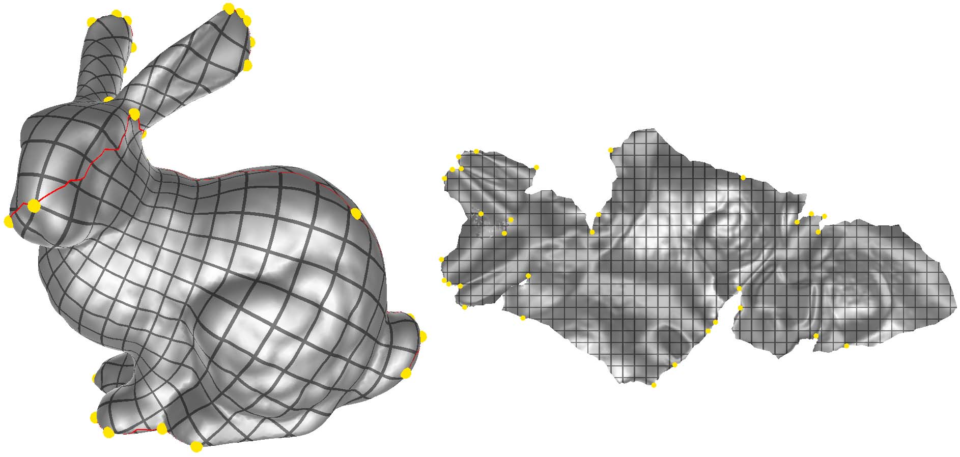
GridDraws a regular grid pattern. (Note that for maps with cones or cuts, grid lines will line up exactly only if the map is made seamless.)
-
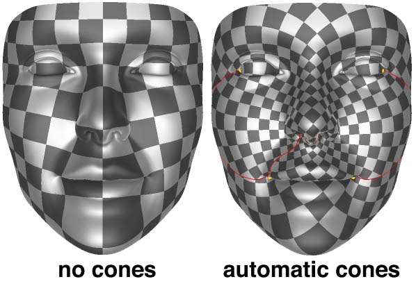
CheckerboardDraws a regular checkerboard pattern. (Note that even for seamless maps there may be a jump from black to white, due to parity considerations.)
-
CirclesDraws random circles. For a map with low angle distortion, these circles should still look like circles (rather than ellipses) on the 3D surface.
The Pattern Scale Slider, found directly below the Pattern Menu, will adjust the scale of the pattern. Such adjustment can be useful for, e.g., understanding what's going on in a map with high area distortion.
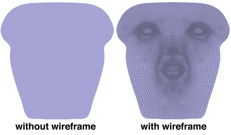
The Show Wireframe checkbox toggles display of a wireframe over the mesh edges, which can be helpful for visualizing the map.
Target Boundary
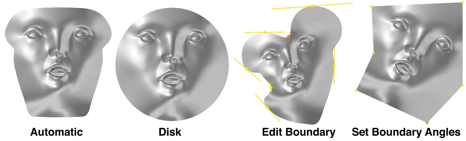
A key functionality provided by BFF is the ability to change the target shape of the flattening, by manipulating its boundary curve. No matter what target shape is used, BFF will tend to reduce a map with very low distortion, so that textures and other data can still be nicely mapped back onto the original surface. Several possibilities are accessible through the graphical interface (and additional possibilities are available through source code-level access):
-
AutomaticIf no special control over the boundary is required, BFF automatically produces the flattening with minimal area distortion. (Note that since we mathematically guarantee that this is the lowest area distortion, it is not possible to reduce area distortion by using different flattening software. However, area distortion can be reduced by adding cuts and cone singularities; see below.)
-
DiskMaps the surface to a circular disk. This map provides an easy way to get a map between two different surfaces (e.g., two different faces): just map each surface to the disk independently, then to locate a point in the 2nd mesh corresponding to a given point on the 1st mesh, follow the maps from the 1st surface, to the disk, and then back to the 2nd surface. (Expert comment: there are Möbius degrees of freedom that are not exposed by the GUI; direct control over these degrees of freedom may be supported in a future release.)
-
Edit BoundaryProvides direct manipulation of the boundary curve using a user-specified spline. Control points can be added (or removed) by clicking (or ctrl-clicking) points on the boundary. Clicking and dragging on a handle will change the scale; holding shift will control the angle instead of the scale.
-
Set Boundary AnglesAllows the corner angles of a polygon to be specified. Angles can be specified using the Angle Control slider, or by typing in the angle box (where the value is interpreted as a multiple of π). As with any polygon, these angles must of course sum to 2π— the GUI will automatically adjust the angles to preserve this sum at all times, by adjusting the angle at the corner that was least-recently updated.
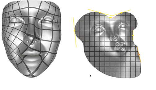
Cone Singularities
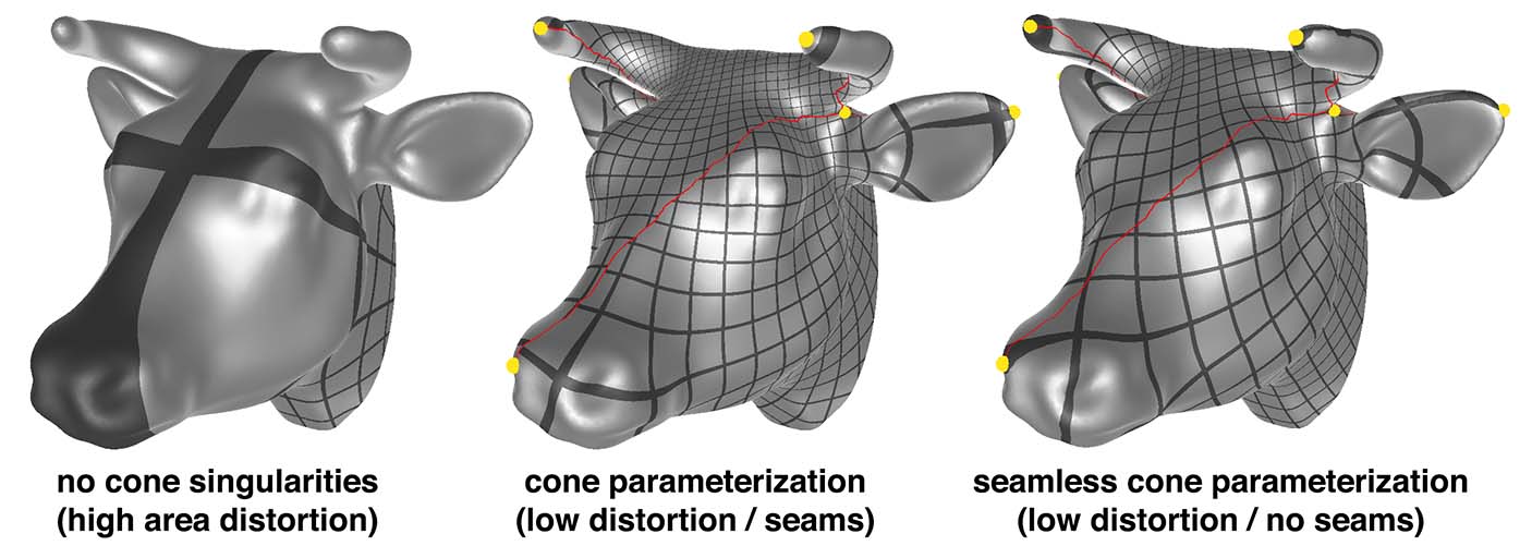
In general, it is impossible to flatten a surface perfectly. Somewhere, there must be distortion of either angles or areas. BFF can produce flattenings with minimal area distortion and virtually zero angle distortion, but in some situations area distortion is still too high for practical use. One solution is to cut the mesh into smaller pieces, each of which is easier to flatten, but typically this is unnecessarily aggressive. One can instead reduce distortion to more reasonable levels by inserting cone singularities, which play much the same role as “darts” in garment design. The BFF GUI makes it easy to explore the effect of placing cones, and also provides the ability to place cones automatically in order to reduce area distortion.
Unlike ordinary cuts, which can cause visual artifacts due to differences in resolution across the cut, BFF guarantees that the map is seamless, meaning that in UV space two corresponding cut edges always have identical length. Seamless maps are discussed in more detail below.
Manual Cone Placement
The easiest way to add cones is simply to click on any point of the surface in either the 3D View or UV View while the target boundary is set to Automatic or Disk. Doing so will insert a cone at the click location, find a cut from this cone to the boundary, and update the flattening. Additional clicks will add additional cones. To see the effect on area distortion, set the plot mode to Area Distortion, which will show the distribution of area distortion over the surface (as described above). Clicking on regions of high area distortion will tend to reduce it. Drawing a pattern (such as grid or checkerboard) will also provide some sense of how much scale distortion remains. Note that a poor choice of cones can actually increase area distortion— some experimentation may be required here. Alternatively, one can try the automatic placement button, as described below. (Cuts are picked automatically in the GUI; the cutting strategy can currently only be changed via source-level modifications to BFF.)
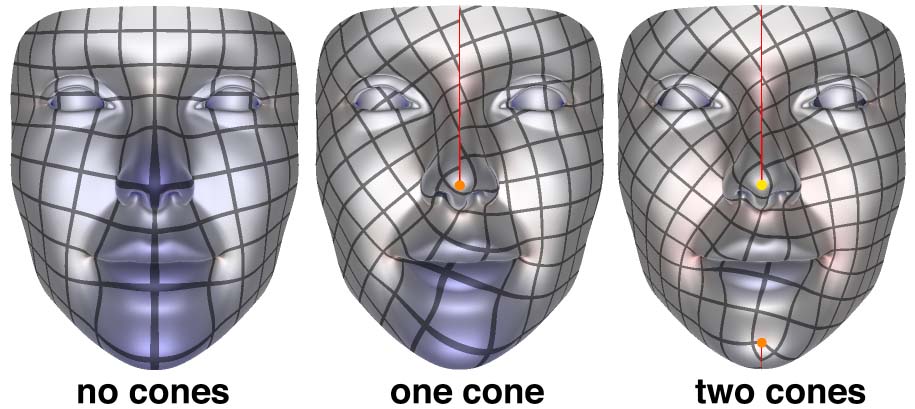
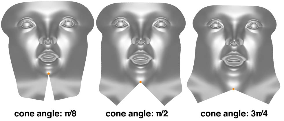
The Angle Control slider allows the cone angle to be adjusted; alternatively, one may type in a specific cone angle (as a multiple of π). The cone angle can be understood in analogy with “darts” in dressmaking: smaller angles will typically accommodate less curvature; large angles are helpful for highly curved regions. For spherical surfaces (with no boundary) the total angle sum must be 4π at all times; the GUI will automatically adjust the least-recently updated cone to make sure this sum holds.
Automatic Cone Placement
A target number of cones can also be placed by simply pressing the Place Cones button. The number of cones can be specified in the # Cones field. Note that computing these cones may take some time, especially for meshes with many boundary vertices. (This feature will be improved in future versions; stay tuned!)
Seamless Maps (Coming soon!)
Placing cones will make cuts in the surface (indicated by red lines). By default, BFF already guarantees that the UV lengths of edges on either side of the cut is guaranteed to be exactly the same, so there is no jump in texture resolution across the cut. Likewise, the angle in UV space between two cut edges is exactly determined by the cone angle—for instance, if all cones angles are a multiple of π/2 (i.e., 90 degrees), then the edges will also be related by 90 degree rotations. To check this, set the drawing pattern to Grid. If all of your cone angles are multiples of π/2, you should see that both the spacing and the direction of grid lines is unchanged as you go across a cut. However, you may also notice that grid lines shift left or right as you cross the cut, resulting in a visible seam. If the surface needs to be covered with a regular pattern (or tessellated into a regular grid), it can be useful to eliminate this seam, which you can do by pressing the Remove Seams button.
Spherical Parameterization
For sphere-like surfaces, BFF will also automatically produce a map to the sphere; simply press the Map to Sphere button. For maps to the sphere, there is less control that can be provided to the user since there is no boundary to edit! (Future versions may expose Möbius degrees of freedom, as with the disk.)
To get a map with lower area distortion, one can again add cone singularities (either automatically or manually) as described above. The surface will automatically be cut into a disk and flattened.
Compiling from source
On Mac OSX and Linux, compiling should be as simple as
git clone https://github.com/GeometryCollective/boundary-first-flattening.git
cd boundary-first-flattening && git submodule update --init --recursive
mkdir build && cd build && cmake ..
make -j 4
These instructions will create a command line and GUI application. The Windows binary shared above was built by linking with the version of OpenBlas included in the deps folder. You will need to include the libopenblas.dll.a static library in your Visual Studio project.
Dependencies
- SuiteSparse (instructions to build SuiteSparse on Windows can be found here)
- OpenGL (version 4.1 or higher)
- OpenGL Mathematics (GLM) (included but not required for command line application)
- Nanogui (included but not required for command line application)
Command line interface
The BFF code can be compiled and run independent of the GUI, for easy integration into other software packages / plugins. To run the command line interface, simply navigate into the directory containing the executable bff-command-line and type
./bff-command-line in.obj out.obj
- --nCones=N_CONES Use the specified number of cone singularities to reduce area distortion (these are chosen automatically)
- --normalizeUVs Scale all UVs so that they are in the range [0,1] x [0,1].
- --writeOnlyUVs Use the vertex flag 'v' in the OBJ format to store UVs (the 'vt' flag is used by default).
- --mapToSphere For a genus-0 surface (no holes, handles, or boundary), computes a flattening over the unit sphere rather than the plane. (See below for more detail.)
- --flattenToDisk For a topological disk, maps to the unit circular disk. (See below for more detail.)
Unlike the GUI, the command line application does not expose some of the interactive features of BFF such editing of boundary lengths, corner angles and cone angles. These features can still be accessed via the code level interface (see below).
Code level interface
All features of BFF can be accessed directly through a static library by compiling the code. The most important methods are described in project/include/Bff.h. These methods assume that a standard triangle mesh has already been loaded into the Mesh object, and produce UV coordinates at the corners of each triangle, stored in the uv member of each element of Mesh::corners.
// Computes automatic flattening with minimal area distortion
//    -boundaryData stores either the target angles at boundary vertices (if
//     givenScaleFactors is false) -OR- the target scale factors (if givenScaleFactors
//     is true)
// (resulting flattening is stored in Corner::uv for each corner of this->mesh)
void BFF::flatten(DenseMatrix& boundaryData, bool givenScaleFactors);


// Computes flattening with prescribed cones
//    - the matrix C is just a Vx1 vector of cone angles (usually zero for most vertices)
//    - surfaceHasCut should be set to true if the locations of cones changed
// (resulting flattening is stored in Corner::uv for each corner of this->mesh)
void BFF::flattenWithCones(const DenseMatrix& C, bool surfaceHasNewCut);


// Uniformization over the unit disk
// (resulting flattening is stored in Corner::uv for each corner of this->mesh)
void BFF::flattenToDisk();


// Conformally maps a genus 0 mesh to a sphere
// (resulting flattening is stored in Corner::uv for each corner of this->mesh)
void BFF::mapToSphere();
Author
Citation
The BFF application implements the algorithm described in the paper:
Boundary First Flattening
Sawhney, Crane
ACM Transactions on Graphics
Our application builds on some terrific insights and work done on conformal flattening in recent years, including the automatic cone placement algorithm found in Ben Chen et al, “Conformal Flattening by Curvature Prescription and Metric Scaling” and the technique used to make maps globally seamless from Springborn et al, “Conformal Equivalence of Triangle Meshes”. We are also indebted to the work of Kharevych et al, “Discrete Conformal Mappings via Circle Patterns”, which introduced the idea of cone singularities into practical conformal parameterization algorithms.
Acknowledgements
Development of this software was funded in part by NSF Award 1717320, and a gift from Autodesk, Inc. Thanks to Tim Davis for help with block reordering and supernodal subfactor extraction in CHOLMOD. Any opinions, findings, and conclusions or recommendations expressed in this material are those of the author(s) and do not necessarily reflect the views of the National Science Foundation.
Awards
BFF is the recipient of the SGP 2019 Outstanding Software Project Award
License
Released under the MIT License